In this project, I used the ESP32 WROOM-32 development board in combination with the Neo-6M GPS module to acquire real-time satellite-based location data. The hardware components were interconnected using hardware serial (UART) to ensure reliable communication between the ESP32 and the GPS module. The wiring setup is illustrated below.
Neo-6M GPS Module | ESP32 WROOM-32
Vcc =====> VIN (3.3V)
GND =====> GND
TX =====> GPIO16
RX =====> GPIO17
Snapshot of the NEO-6M GPS Module used in this project:
Front View of the NEO-6M GPS Module
Backside of the NEO-6M GPS Module
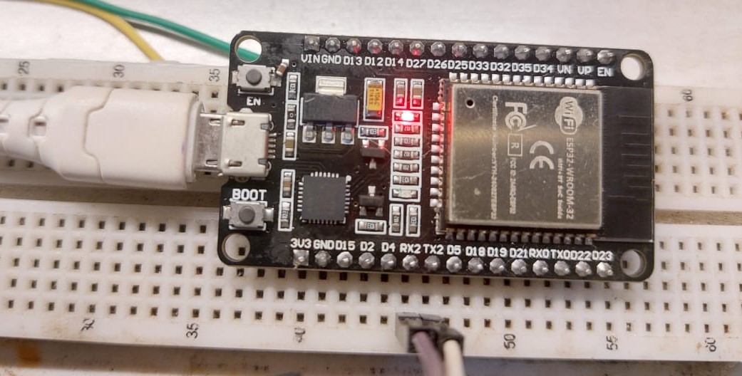
Snapshot of the ESP32 WROOM-32 Arduino board used in this project:
After the interconnecting these two boards you have to follow following procedures.
Install TinyGPS++ library:
- Open Arduino
IDE → Go to Sketch → Include Library → Manage
Libraries.
- Search
TinyGPS++ and install it.
Connect ESP32 via USB and select the correct board:
- Tools
→ Board → ESP32 WROOM DA module
- Tools
→ Port → Select your ESP32’s port.
My board and port selection as follows:
Upload the code and open Serial Monitor (115200 baud).
Use following Arduino code read the GPS and write the results on the serial monitor.
#include <HardwareSerial.h>
#include <TinyGPS++.h>
static const int RXPin = 16, TXPin = 17; // ESP32 Hardware Serial pins
static const uint32_t GPSBaud = 9600; // Default baud rate of Neo-6M
TinyGPSPlus gps;
HardwareSerial gpsSerial(1); // Using UART1
void setup() {
Serial.begin(115200); // Monitor serial
gpsSerial.begin(GPSBaud, SERIAL_8N1, RXPin, TXPin);
Serial.println("GPS Module is starting...");
}
void loop() {
while (gpsSerial.available()) {
gps.encode(gpsSerial.read()); // Parse GPS data
if (gps.location.isUpdated()) {
Serial.print("Latitude: ");
Serial.print(gps.location.lat(), 6);
Serial.print(" Longitude: ");
Serial.print(gps.location.lng(), 6);
Serial.print(" Speed: ");
Serial.print(gps.speed.kmph());
Serial.println(" km/h");
}
}
}
Once the GPS module locks onto satellites, LED of the GPS will start to blink. then you will see Latitude,
Longitude, and Speed in the Serial Monitor as follows:
Finally, my overall setup can be denote as this.


Comments
Post a Comment